Help documentation
LED display data group exchange, no need to panic if the cable is misplaced, this function will help you
Have you encountered such a problem: when installing the LED display, sometimes we first install the modules, cables, power supplies and other hardware before debugging. This installation order often reverses the cable sequence, resulting in The display screen is misplaced, and it is more troublesome to replace the cable. If it is a wall-mounted display, it is easy to bump the module lamp beads, so what should I do? This issue teaches you how to solve similar problems with the data group exchange function.
What is a data set?
To put it simply, one R signal of the monochrome module is a set of data; the two signals of R and G of the two-color module are a set of data; the three signals of R, G, and B of the full-color module are a set of data.
How many sets of data a module has, we can judge by its interface definition. The common interface of full-color module is HUB75 interface, and the interface definition is as follows:
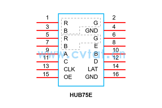
According to the interface definition in the above figure, it can be seen that the HUB75 interface has 2 groups of RGB data groups.
How to set up the exchange of data sets?
As shown in the figure below: Take the 800mm*800mm size P5 box + R508T receiving card as an example, the second interface of the receiving card is connected to the third row module of the box, and the third interface of the receiving card is connected to the second row of the box. group (that is, the order of ports 2 and 3 is reversed), resulting in the dislocation of the second and third rows of the cabinet.
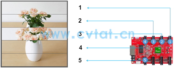
Without reconnecting the cable, we can realize the normal display of the cabinet screen by exchanging the data group of the second interface of the receiving card and the data group of the third interface.
Data set exchange settings
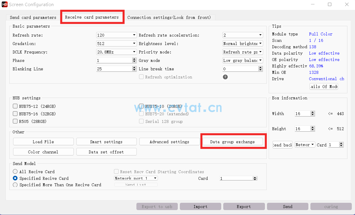
1. Enter the "Receiver Card Parameters" interface in the HDSet software;
2. Click the "Data Group Exchange" button;
3. Check "Enable", then change the data groups of interface 2 to 5 and 6, and the data groups of interface 3 to 3 and 4.
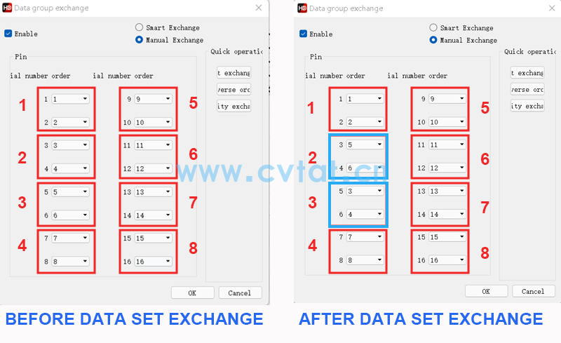
4. Click the "OK" button to exit, and then click the "Send" button.
In addition, when a certain interface of the receiving card fails, the data of the faulty interface can also be output from the idle interface through the data group switching function.
Categories
Product
- P5 Indoor RGB LED Display LED Screen Pan
- P4 Indoor RGB LED Display LED Screen Pan
- P4 Indoor RGB LED Display LED Screen Pan
- P4 Indoor RGB LED Display LED Screen Pan
- P3 Outdoor LED Display panel full colour
- P4 Outdoor LED Display panel full colour
- P4 Outdoor LED Display panel full colour
- P5 Outdoor LED Display panel full colour
- P3.91 Outdoor Waterproof Die Casting Alu
- P3.91 Outdoor Waterproof Rental LED disp
Contact Us
Contact: CVTAT LED Display
E-mail: z@cvtat.cn
Add: Wanda Industrial Park, Shiyan Town, Baoan District, Shenzhen City, Guangdong Province, China

WhatsApp scan
code follow us